Camera calibration computes the intrinsic parameters — focal length, principal point, and distortion coefficients — that describe how your specific camera maps the 3D world onto a 2D sensor. Without accurate intrinsics, every downstream step (pose estimation, hand-eye calibration, sim placement) inherits the error silently. This post covers how to get them right using a ChArUco board and the current OpenCV 4.7+ API.
1. Why Camera Calibration Is the Unglamorous Step That Breaks Everything
Every downstream component that depends on vision — pose estimation, object detection, sim-to-real transfer, hand-eye calibration — inherits whatever error lives in your camera model. A robot arm reaching for an object does not fail dramatically because of a bad calibration. It misses by a centimetre. It picks at the wrong angle. These are the kinds of errors that look like algorithm problems, feel like hardware problems, and are actually calibration problems.
This becomes even more consequential when the goal is to generate synthetic training data in simulation. If the virtual camera does not accurately replicate the real one, the data the robot trains on does not match what it sees in the real world. The sim-to-real gap does not start at the policy level. It starts here, at calibration.
We encountered this first-hand while setting up a synthetic data generation pipeline — and that process starts with correctly computing intrinsic parameters, which is what this post covers.
2. Intrinsic Parameters and Why ChArUco Is the Right Tool to Get Them
A camera projects a three-dimensional scene onto a flat sensor, and intrinsic parameters are the numbers that describe exactly how that projection works. There are three things they give you:
Focal length — the zoom factor in pixels. If this is wrong, your distance and scale estimates are wrong.
Principal point — where the optical axis actually lands on the sensor. For a 1920×1080 camera you might expect dead centre, but it is almost never exactly there. That small offset compounds across the frame and introduces systematic positional error.
Distortion coefficients — no physical lens is perfect. These numbers model how the lens bends straight lines into curves, and allow OpenCV to correct for it.
Together they form the camera matrix and distortion vector — the two outputs every downstream step in your pipeline will depend on.
Camera Matrix:          Distortion Coefficients:
[[fx,  0, cx],          [k1, k2, p1, p2, k3]
 [ 0, fy, cy],
 [ 0,  0,  1]]
Intrinsics are camera-specific, not scene-specific. Calibrate once per camera, store the result, and reuse it until the hardware changes — with one important condition: the camera must have fixed optics. If autofocus is enabled, the lens shifts slightly with every focus adjustment, and the focal length changes with it. The calibration you computed at one focus distance is no longer valid at another. Before calibrating, disable autofocus and lock the focus manually. The same applies to variable zoom — any zoom change invalidates the calibration entirely. For robotics applications, a fixed-focus lens is the simplest and most reliable choice. If your camera does not support focus lock, treat any focus change as a recalibration trigger.
Getting these numbers requires a calibration target. We use a ChArUco board — here is why.
The default in most tutorials is a plain chessboard. It works, but it is fragile: if any part of the board is blocked or leaves the frame, the entire detection fails. OpenCV needs the complete pattern visible, all at once.
ArUco markers solve the occlusion problem — each marker has a unique ID so partial views are detected — but their corners are less precise, which matters for calibration.
ChArUco combines both: ArUco markers embedded inside a chessboard grid. The markers handle identification; the chessboard intersections provide subpixel-accurate corners. A partial view with six visible corners gives you six valid correspondences. No frame is wasted.
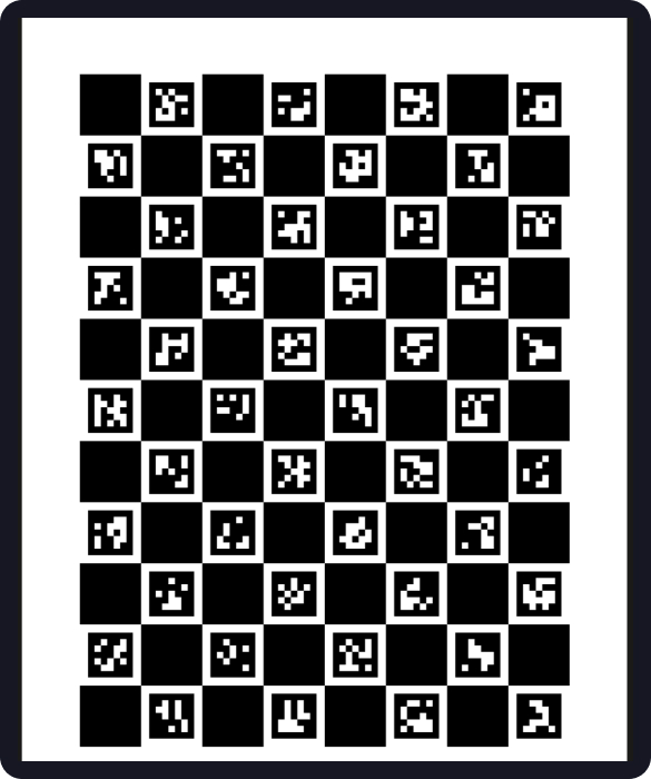
For our setup we use a board 8 squares wide × 11 squares tall with the DICT_5X5_100 dictionary, with squares measured at 30.01 mm and markers at 22.01 mm. Those decimal values come from physical measurement with calipers — the calibration algorithm treats them as ground truth, so print on a rigid flat surface and measure what you actually printed.
The default calibration model — five parameters [k1, k2, p1, p2, k3] — works well for most standard lenses up to roughly 90° field of view. For wider lenses, add cv2.CALIB_RATIONAL_MODEL to the calibration flags to fit an 8-parameter model. For true fisheye lenses (120°+), the Brown-Conrady model breaks down at the periphery entirely — use cv2.fisheye.calibrate with the Kannala-Brandt model instead.
3. Capturing Good Frames and Running the Calibration
Most tutorials tell you to take 20 images of the board. The number is not wrong — the mindset is. Twenty identical frames taken from the same distance and angle produce a calibration that fits that specific geometry and breaks everywhere else.
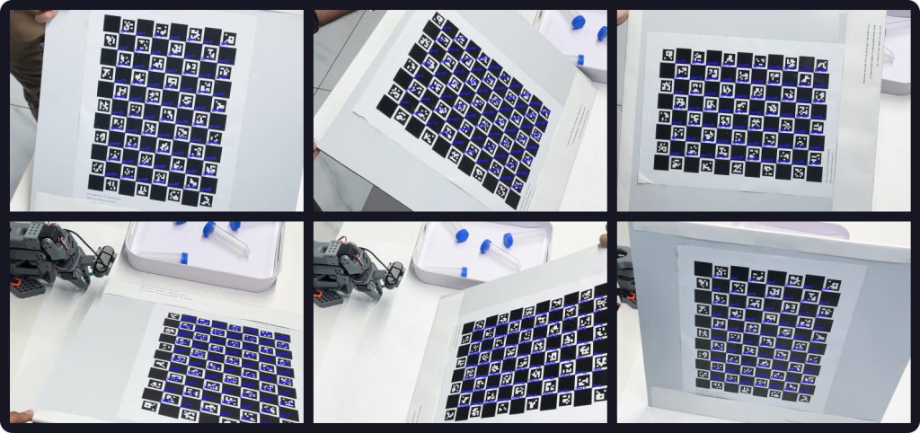
What the algorithm needs is geometric diversity — variation in position, tilt, distance, and rotation. Think of it less as taking photos and more as sampling the space of possible camera-to-board relationships.
In practice this means: move the board across all four quadrants of the frame, tilt it steeply (30–60°) not just flat-on, vary the distance, and deliberately let it partially leave the frame. Edge coverage is particularly important — distortion is most pronounced at the periphery and will be underconstrained if all your corners land in the centre. Aim for at least 20 accepted frames with a minimum of 6 detected corners each.
Keep the camera fixed and move the board. Once you have a good set, here is the calibration code using the current OpenCV 4.7+ API:
import cv2
import numpy as np

# Board: 8 squares wide x 11 squares tall
ARUCO_DICT = cv2.aruco.getPredefinedDictionary(cv2.aruco.DICT_5X5_100)
BOARD = cv2.aruco.CharucoBoard(
    size=(8, 11), squareLength=0.03001, markerLength=0.02201, dictionary=ARUCO_DICT
)

# Detector — use CORNER_REFINE_SUBPIX (CONTOUR is broken in 4.7+)
detector_params = cv2.aruco.DetectorParameters()
detector_params.cornerRefinementMethod = cv2.aruco.CORNER_REFINE_SUBPIX
detector = cv2.aruco.CharucoDetector(
    BOARD, cv2.aruco.CharucoParameters(), detector_params
)

# Collect corners across frames
all_obj_pts, all_img_pts, image_size = [], [], None

for image_path in image_paths:
    gray = cv2.cvtColor(cv2.imread(image_path), cv2.COLOR_BGR2GRAY)
    corners, ids, _, _ = detector.detectBoard(gray)

    if ids is not None and len(ids) >= 6:
        obj_pts, img_pts = BOARD.matchImagePoints(corners, ids)
        if obj_pts is not None:
            all_obj_pts.append(obj_pts)
            all_img_pts.append(img_pts)
            image_size = image_size or gray.shape[::-1]

# Run calibration
ret, camera_matrix, dist_coeffs, rvecs, tvecs = cv2.calibrateCamera(
    all_obj_pts, all_img_pts, image_size, None, None
)

np.save("camera_matrix.npy", camera_matrix)
np.save("dist_coeffs.npy", dist_coeffs)
Two things worth noting here. First, calibrateCameraCharuco() — the function most older tutorials use — was removed in OpenCV 4.7. The replacement is board.matchImagePoints() feeding into the standard calibrateCamera(). Second, CORNER_REFINE_CONTOUR was silently broken in 4.7 and performs no subpixel refinement at all — always use CORNER_REFINE_SUBPIX for calibration.
4. Reading the Results: What Reprojection Error Tells You
The first value returned by calibrateCamera() is the reprojection error — your primary quality signal. It measures, in pixels, how far off the calibrated camera model is from the actual detected corner positions. Lower is better; for robotics, under 0.5 px is the practical target — though note this threshold is resolution-dependent: 0.5 px on a 4K sensor represents a smaller physical error than on a 720p one, so tighten the bar accordingly as resolution increases.
| Reprojection Error | Assessment |
|---|---|
| < 0.3 px | Excellent |
| 0.3 – 0.5 px | Good — suitable for most robotics applications |
| 0.5 – 1.0 px | Acceptable — investigate outlier frames |
| > 1.0 px | Poor — do not use downstream |
A high number usually means one of three things: poor capture diversity (frames were too similar), outlier frames with blur or bad detections, or a physical board problem like a warped print or wrong measurements.
One important caveat: a good global average is necessary but not sufficient. A calibration done entirely with frontal, centre-frame images can report 0.2 px error while failing at the edges of the frame or at different depths. The number confirms the model fits your data — it does not guarantee the data was representative.
Per-frame error is more informative than the average alone. Going one step further, look at where residuals cluster spatially — if errors are consistently higher in one region of the image, that region was underrepresented in your capture set and the distortion model there is poorly constrained.
for i, (obj_pts, img_pts, rvec, tvec) in enumerate(
    zip(all_obj_pts, all_img_pts, rvecs, tvecs)
):
    projected, _ = cv2.projectPoints(obj_pts, rvec, tvec, camera_matrix, dist_coeffs)
    error = cv2.norm(img_pts, projected, cv2.NORM_L2) / len(projected)
    print(f"Frame {i:02d}: {error:.4f} px")
Frames with error well above the mean are worth inspecting and discarding. Removing the two or three worst offenders and re-running often brings the result into an acceptable range.
5. Understanding Your Outputs
A successful calibration produces two files — a camera matrix and a distortion coefficient vector. These travel with the camera through every downstream step.
The camera matrix for a 1920×1080 camera looks something like:
[[1412.3,    0.0,  963.7],
 [   0.0, 1410.8,  541.2],
 [   0.0,    0.0,    1.0]]
The diagonal values are focal lengths in pixels. The top-right values are the principal point — notice it is (963.7, 541.2), not the expected image centre of (960, 540). That offset is real and meaningful. One thing to keep in mind: the camera matrix is resolution-dependent. If you calibrate at full resolution and run inference at a lower one, the matrix must be scaled proportionally. This holds for uniform downscaling — for cropping, the effective principal point shifts and the matrix must be recomputed, not just scaled. Distortion coefficients describe the lens optics and are not affected by either.
A quick visual sanity check before using these values downstream:
img = cv2.imread("any_calibration_frame.jpg")
undistorted = cv2.undistort(img, camera_matrix, dist_coeffs)
cv2.imwrite("undistorted_check.jpg", undistorted)
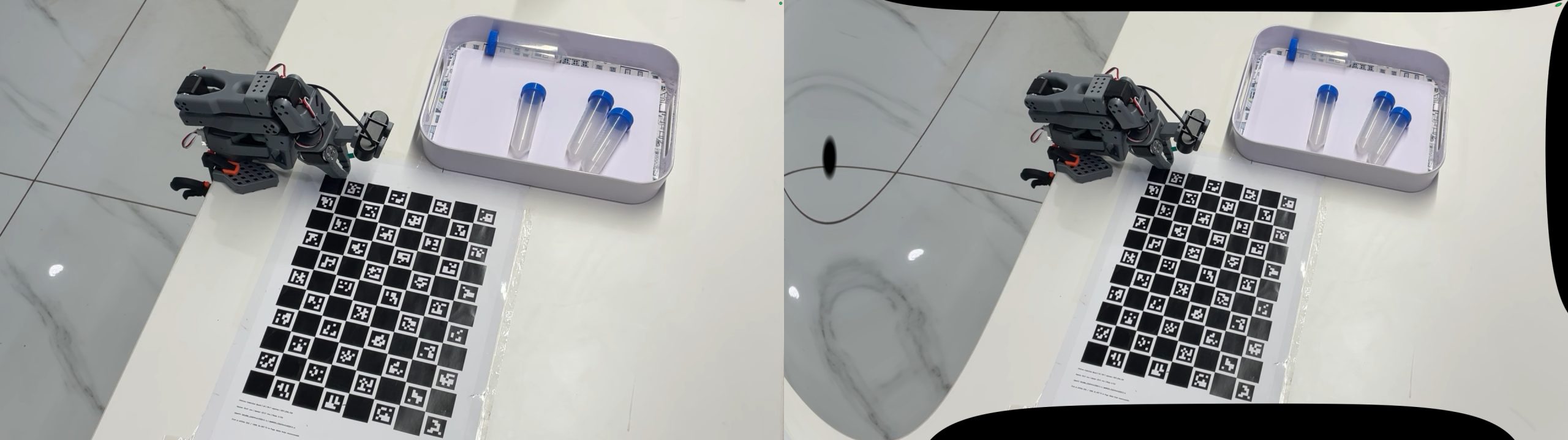
Look at straight edges in the scene. In the original they may curve near the corners. In the undistorted version they should be straight. If they curve in the opposite direction, the distortion coefficients have the wrong sign — which usually traces back to a board measurement error.
These two files are the foundation for everything that follows — pose estimation, hand-eye calibration, and accurate camera placement in simulation. Getting them right, and knowing how to verify them, is what the rest of the pipeline depends on.