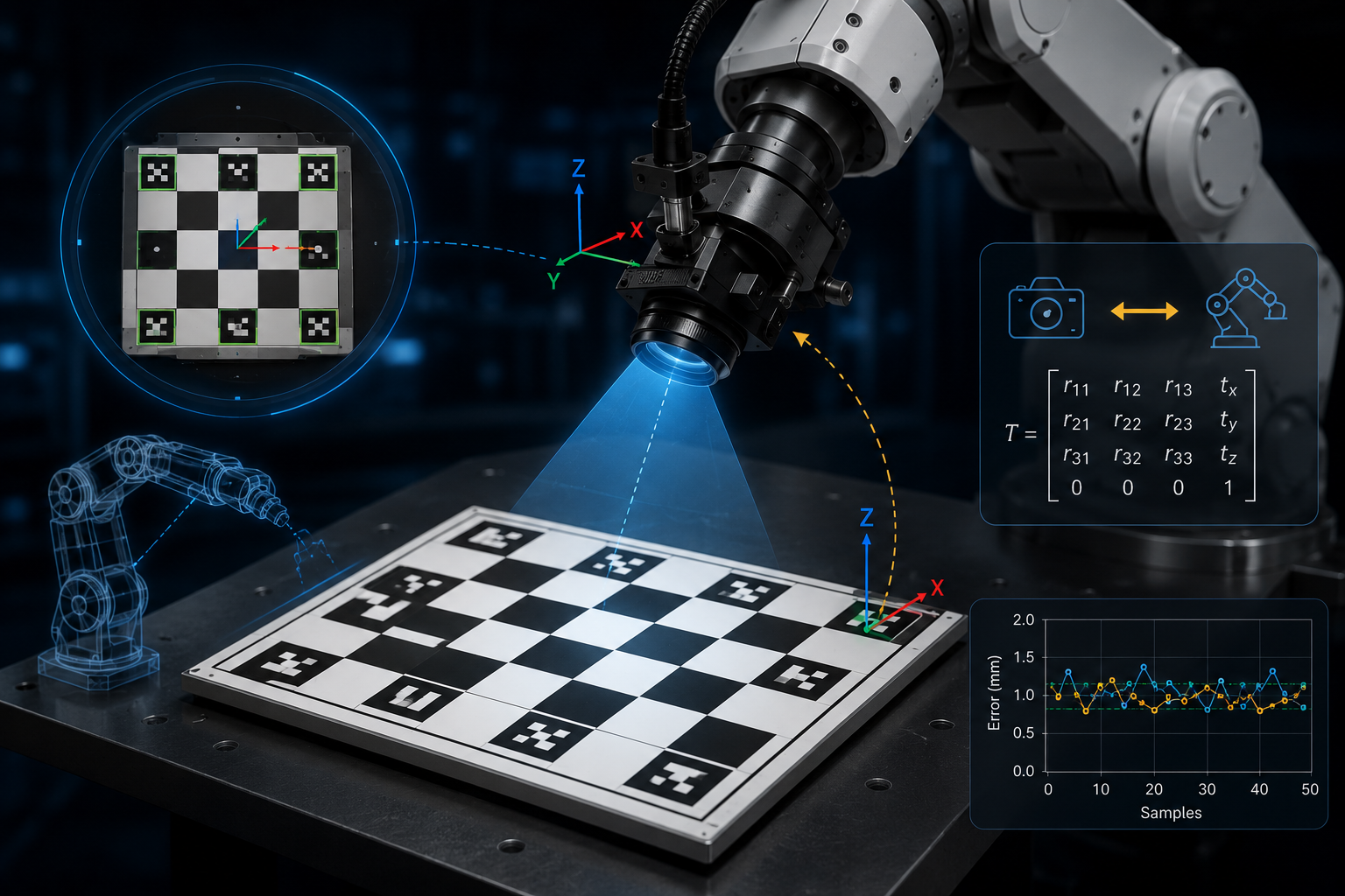
Camera calibration makes vision measurable. Hand–eye calibration makes that vision usable by the robot.
What this post covers
1. From calibrated vision to robot-aware vision
The previous ChArUco camera calibration step produced camera_matrix.npy and dist_coeffs.npy. Those files made the wrist camera geometrically reliable; this step connects that calibrated camera to the robot so detections can become motion targets.
In other words, camera calibration answered: how does this camera measure the world? Hand–eye calibration answers the next question: where is this camera relative to the robot hand?
2. What hand–eye calibration is and why it matters
In robotics, the hand is the robot end-effector, wrist, flange, or gripper. The eye is the camera. Hand–eye calibration estimates the fixed 3D transform between those two coordinate frames.
For a wrist-mounted camera, the key result is usually:
T_gripper_camera
This is a 4×4 homogeneous transformation matrix. It contains both translation and rotation. Translation tells how far the camera is from the wrist frame. Rotation tells how the camera axes are oriented relative to the wrist axes.
Simple definition: hand–eye calibration teaches the robot where its camera is. After calibration, a point detected in the camera frame can be converted into the robot frame.
The reason this matters is practical: the camera reports positions in the camera coordinate frame, while the robot plans motion in the robot base or end-effector frame.
object in camera frame → hand–eye transform → object in robot base frame → robot motion target
That conversion is useful for pick-and-place, bin picking, tabletop grasping, visual servoing, inspection, tool positioning, marker-based alignment, and sim-to-real workflows where camera geometry has to line up with robot geometry.
3. Where we used it: the SO-101 pipeline
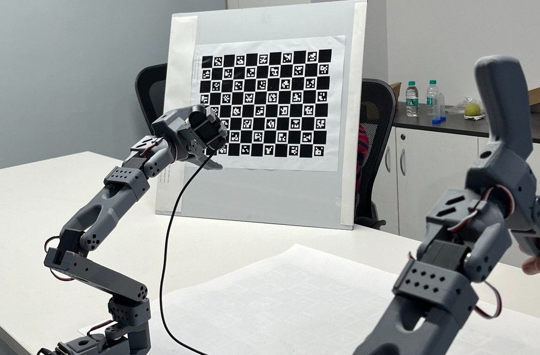
For our implementation, we performed eye-in-hand calibration on an SO-101 arm with a camera mounted on the wrist. The ChArUco board stayed fixed on the table, while the wrist camera moved through different poses.
Use the already calibrated camera intrinsics: camera_matrix.npy and dist_coeffs.npy.
Fix the ChArUco board on the table so it does not move during capture.
Move the wrist camera to multiple distinct poses.
For each pose, save the robot wrist transform T_base_gripper.
For the same image, detect the ChArUco board and estimate T_camera_charuco.
Pass all pose pairs to cv.calibrateHandEye().
Save the final transform as T_gripper_camera.npy.
The important transform chain for eye-in-hand calibration is:
T_base_charuco = T_base_gripper × T_gripper_camera × T_camera_charuco
The calibration target is fixed in the real world, so after a good calibration, every captured pose should predict almost the same T_base_charuco.
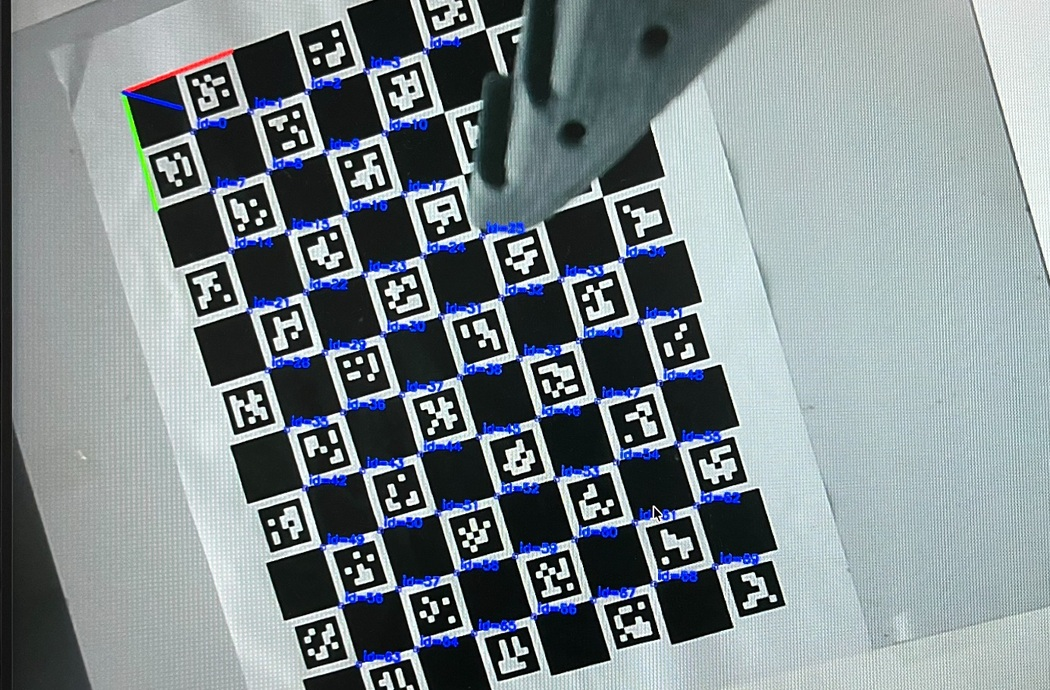
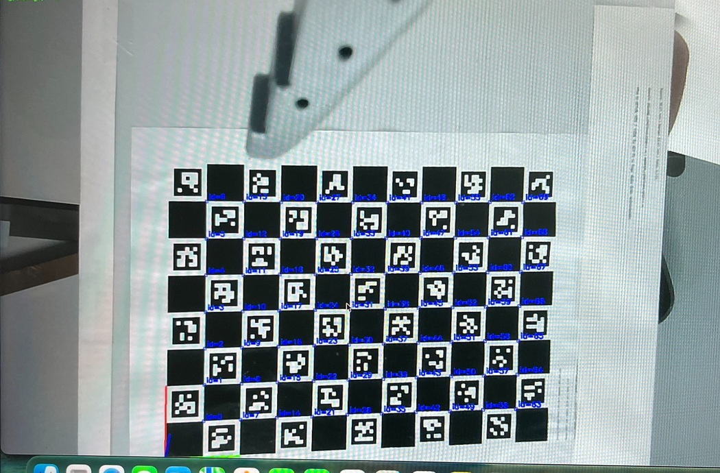
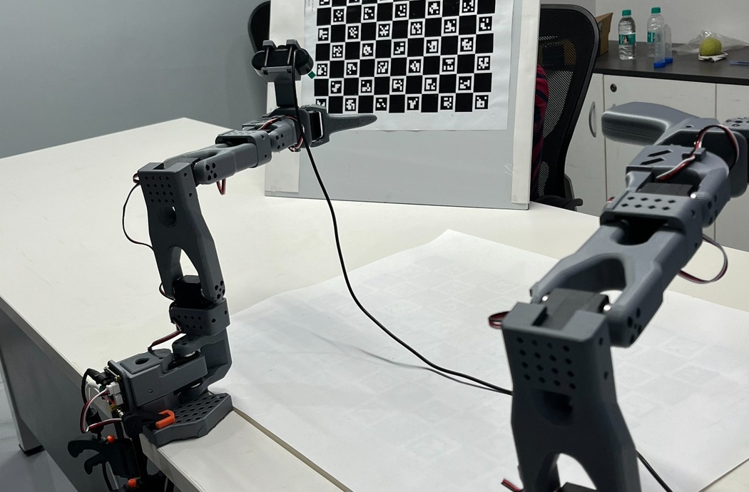
Visuals from the hand–eye calibration setup
These cropped visuals show the real SO-101 wrist-camera setup used during calibration: the board view from the camera, the robot arm, and the fixed target used for multiple robot poses.
4. Solving and choosing a method
OpenCV supports several hand–eye solvers through cv.calibrateHandEye(). We treated the methods as candidates, not as universal rankings. Method performance is data-dependent: pose diversity, rotation noise, translation noise, robot accuracy, and target detection quality can all change which method behaves best. Published comparisons also show that noise type and motion range matter, so the safest workflow is to try multiple methods and compare consistency rather than trusting one result blindly.
| Method | How we treated it | Practical note |
|---|---|---|
| TSAI | Good first baseline for most eye-in-hand calibrations. | Stable when the pose set is clean and diverse, but still compare it against other methods. |
| PARK | Useful cross-check when the dataset has strong rotation diversity. | Helpful for checking whether the rotation result agrees with TSAI. |
| HORAUD | Another classical separable solution to compare against. | Confidence improves when HORAUD is close to TSAI/PARK. |
| ANDREFF | Worth trying when the motion set is rich and a simultaneous solution is useful. | Can be less forgiving if poses are too similar or noisy. |
| DANIILIDIS | Useful as a dual-quaternion style alternative for coupled rotation/translation. | Compare carefully; noisy samples can change the translation result. |
Run all five methods, then compare mean/max fixed-board validation error, transform consistency, physical plausibility of the camera mount, and the touch-test result. If several methods agree closely, the dataset is usually healthy. If the results split apart, inspect pose diversity, target movement, robot pose accuracy, unit consistency, and outlier frames before trusting the output.
Capturing the two inputs the solver needs
The solver needs synchronized robot poses and camera target poses. The robot side is T_base_gripper. The camera side is T_camera_charuco. For SO-101, the joint readings can be pulled through LeRobot’s SO101 follower interface, then converted to T_base_gripper with the same FK model or URDF used by the robot stack. The important contract is simple: each saved image must be paired with the 4×4 wrist pose from the same physical moment.
This is the concrete capture pattern we used conceptually. The exact FK helper is project-specific, but the robot-state read is not just a placeholder: it follows the SO-101 follower API style, where the robot is configured with its serial port and id, connected, and read through get_observation().
# 1) Robot side: read SO-101 follower joint positions with LeRobot.
from lerobot.common.robots.so101_follower import (
    SO101Follower,
    SO101FollowerConfig,
)
robot_cfg = SO101FollowerConfig(
    port="/dev/ttyACM0",    # your MotorBus port
    id="my_so101_follower", # same id used during calibration
    use_degrees=True,
)
robot = SO101Follower(robot_cfg)
robot.connect(calibrate=False)
obs = robot.get_observation()
joint_positions = {
    "shoulder_pan": obs["shoulder_pan.pos"],
    "shoulder_lift": obs["shoulder_lift.pos"],
    "elbow_flex": obs["elbow_flex.pos"],
    "wrist_flex": obs["wrist_flex.pos"],
    "wrist_roll": obs["wrist_roll.pos"],
    "gripper": obs["gripper.pos"],
}
# Convert calibrated joint positions to the wrist pose used by hand-eye.
# This function comes from your SO-101 URDF/DH model or robot stack.
T_base_gripper = so101_fk_to_matrix(joint_positions)
# If your control stack already exposes an end-effector pose, use that
# instead, but keep the output as a 4 x 4 T_base_gripper matrix.

# 2) Camera side: estimate the fixed board pose from the wrist camera image.
# K and D are camera_matrix.npy and dist_coeffs.npy from ChArUco camera calibration.
marker_corners, marker_ids, _ = cv.aruco.detectMarkers(gray, aruco_dict)
_, charuco_corners, charuco_ids = cv.aruco.interpolateCornersCharuco(
    marker_corners, marker_ids, gray, board, K, D
)
ok, rvec, tvec = cv.aruco.estimatePoseCharucoBoard(
    charuco_corners, charuco_ids, board, K, D, None, None
)
R, _ = cv.Rodrigues(rvec)
T_camera_charuco = make_T(R, tvec)
If FK is not integrated during live capture, log the obs dictionary beside each saved image and convert those joint positions to T_base_gripper offline before running the solver. What matters is synchronization and using the same calibrated robot id, units, and wrist frame every time.
Solving the hand–eye transform
After comparing methods, the calibration call itself is small. The example below shows the baseline call pattern using TSAI; in practice we ran the same block for all five methods and selected the result that validated best.
import cv2 as cv
import numpy as np

R_gripper2base = []
t_gripper2base = []
R_target2cam = []
t_target2cam = []

for T_bg, T_ct in zip(T_base_gripper_all, T_camera_charuco_all):
    R_gripper2base.append(T_bg[:3, :3])
    t_gripper2base.append(T_bg[:3, 3].reshape(3, 1))
    R_target2cam.append(T_ct[:3, :3])
    t_target2cam.append(T_ct[:3, 3].reshape(3, 1))

R_cam2gripper, t_cam2gripper = cv.calibrateHandEye(
    R_gripper2base,
    t_gripper2base,
    R_target2cam,
    t_target2cam,
    method=cv.CALIB_HAND_EYE_TSAI,
)

T_gripper_camera = np.eye(4)
T_gripper_camera[:3, :3] = R_cam2gripper
T_gripper_camera[:3, 3] = t_cam2gripper.reshape(3)
np.save("outputs/T_gripper_camera.npy", T_gripper_camera)
Once this file exists, detections from the wrist camera can be converted into robot coordinates:
tmp = np.matmul(T_base_gripper, T_gripper_camera)
T_base_object = np.matmul(tmp, T_camera_object)
Files produced by the pipeline
| File | Where it comes from | Purpose |
|---|---|---|
| camera_matrix.npy | ChArUco camera calibration | Stores focal length and principal point. |
| dist_coeffs.npy | ChArUco camera calibration | Stores lens distortion coefficients. |
| handeye_samples.npz | Sample capture step | Stores T_base_gripper, T_camera_charuco, timestamps, image paths, and optional errors. |
| T_gripper_camera.npy | Hand-eye solver output | The final fixed camera-to-wrist transform used in robot vision. |
| sample_###.png | Saved capture frames | Useful for debugging bad detections and removing weak samples. |
5. Checking the result
There are two different checks that often get mixed together.
This is measured in pixels. It checks whether the camera model and detected board pose project known ChArUco points back onto the image where the detector actually saw them. A low reprojection error means the image-based board pose is reliable. It does not, by itself, prove that the robot-camera transform is correct.
projected, _ = cv.projectPoints(
    object_points,
    rvec,
    tvec,
    camera_matrix,
    dist_coeffs,
)
error_px = cv.norm(
    image_points,
    projected,
    cv.NORM_L2,
) / len(projected)
print(f"reprojection error: {error_px:.4f} px")
For the hand-eye result, the more practical check is target consistency. Because the ChArUco board was fixed on the table, every robot-camera sample should estimate the board at the same position in the robot base frame.
T_gripper_camera = np.load("outputs/T_gripper_camera.npy")
data = np.load("data/handeye_samples.npz")

base_positions = []
for T_bg, T_ct in zip(data["T_base_gripper"], data["T_camera_charuco"]):
    tmp = np.matmul(T_bg, T_gripper_camera)
    T_base_charuco = np.matmul(tmp, T_ct)
    base_positions.append(T_base_charuco[:3, 3])

base_positions = np.asarray(base_positions)
mean_position = base_positions.mean(axis=0)
errors_mm = np.linalg.norm(
    base_positions - mean_position,
    axis=1,
) * 1000.0
print("mean error mm:", errors_mm.mean())
print("max error mm:", errors_mm.max())
Optional weak-frame filtering before the final solve
Outlier rejection should not be used to hide a bad calibration. We used it only after inspecting the saved images and robot logs, then removed samples that were visibly blurred, partially detected, or inconsistent with the fixed-board assumption.
# After a first solve, reject samples whose fixed-board position
# is an outlier. Then re-run calibrateHandEye on the filtered set.
median = np.median(errors_mm)
mad = np.median(np.abs(errors_mm - median)) + 1e-9
robust_sigma = 1.4826 * mad
keep = errors_mm < (median + 3.0 * robust_sigma)
print(f"keeping {keep.sum()} of {len(keep)} samples")

filtered = {
    "T_base_gripper": data["T_base_gripper"][keep],
    "T_camera_charuco": data["T_camera_charuco"][keep],
}
np.savez("data/handeye_samples_filtered.npz", **filtered)
# Re-run the solver on handeye_samples_filtered.npz and compare:
# - mean/max fixed-board error
# - camera mount plausibility
# - physical touch-test accuracy
A good filtering rule is conservative: remove obvious bad samples, then compare the filtered and unfiltered transforms. If filtering changes the transform dramatically, the dataset likely needs to be recaptured with better pose diversity or cleaner detections.
In our run, the initial validation error was around 33 mm. After improving pose diversity, image quality, and weak-frame filtering, the validation result was reduced to around 12 mm. We mention those numbers only as our prototype result, not as a universal benchmark.
Making error targets task-specific
Important framing: the targets below are practical prototype / hobbyist-arm rules of thumb for a low-cost robot setup like our SO-101 workflow. Industrial systems with rigid robots and metrology-grade cameras often expect much tighter residuals: sub-millimeter for smaller robots and millimeter-level for larger robots. Treat the table as task guidance for this class of prototype system, not an industry-wide accuracy standard.
| Task type | Prototype target | What it means in practice |
|---|---|---|
| Coarse reaching / large objects | About 10–15 mm | Usually usable for moving near a target, rough alignment, or large grasp zones. |
| General tabletop grasping | About 5–10 mm | Better for repeatable pick points where object size gives some tolerance. |
| Small-part bin picking | Prefer less than 5 mm | Needed when object features are small or the gripper has little clearance. |
| Precision insertion / screwdriving | Prefer less than 2 mm | Usually also needs TCP calibration, compliance, visual servoing, or task-specific offsets. |
| Low-cost prototype arm | Often 10–20 mm is realistic | Still useful if the task has tolerance; always verify with actual robot motion. |
Another reason to treat the number carefully is error compounding. A small transform error near the wrist can become a larger miss at the fingertips, especially when the tool is long or the robot approaches at an angle. That is why the final question is not just “what was the residual?” but “did the robot touch or grasp the thing it was supposed to?”
6. Validating beyond the numbers
A good calibration should pass more than one test. We used numerical validation, but a task-level check is equally important.
Compute T_base_charuco for every sample and check the spread in millimeters.
Look at the worst samples and remove frames with blur, partial board visibility, or suspicious robot poses.
Verify that the output is used as T_gripper_camera, not its inverse.
Verify the tool-center point or gripper tip frame before judging hand-eye accuracy at the fingertips. Hand-eye calibrates camera-to-wrist; it does not fix a wrong tool-tip offset.
Detect a point or marker and command the robot to touch it with a known tool tip. This checks the full camera-robot-task chain, not just the solver.
Run the intended pick or reach behavior repeatedly and measure miss distance under the same conditions in which the robot will operate.
Physical validation is important because a calibration can look acceptable numerically while still failing at the tool tip if the TCP, gripper offset, robot kinematics, or transform direction is wrong.
7. Challenges and what we did about them
Hand-eye calibration looks simple on paper, but the practical details matter. The table below summarizes the issues we faced and the fixes that made the result more reliable.
| Challenge | Why it matters | What helped |
|---|---|---|
| Camera intrinsics must be correct | Bad intrinsics silently corrupt every ChArUco pose. | Start from a verified ChArUco camera calibration and keep the same focus/resolution. |
| Pose diversity | Similar poses make the solver weak and can hide rotation errors. | Use more than the minimum number of poses and include wrist rotations, not just translation. |
| Robot pose accuracy | Wrong FK, wrong frame, or manual pose mismatch directly increases error. | Record the wrist pose at the same moment as the image and keep units consistent. |
| TCP or tool-tip frame | Hand-eye calibration estimates camera-to-wrist. If the TCP or gripper-tip frame is wrong, the robot can still miss even with a good camera transform. | Calibrate or verify the TCP separately, then run a physical touch test using the actual tool tip used in the task. |
| Board movement | For eye-in-hand, the board must be static. Any movement becomes calibration noise. | Fix the board rigidly on the table and do not touch it during capture. |
| Detection quality | Blur, glare, small markers, and edge-of-frame views make T_camera_charuco noisy. | Keep the board in focus, well exposed, centered, and fully visible. |
| OpenCV API differences | ArUco and ChArUco function names and arguments vary across OpenCV versions. | Use version-compatible code and keep the contrib package installed. |
| Linux camera and GUI issues | Camera indices, Wayland, Qt, and OpenCV GUI backends can interrupt capture. | Use stable camera paths such as /dev/videoX, save images, and support console validation when needed. |
| Transform direction mistakes | Using T_camera_gripper when code expects T_gripper_camera creates large errors. | Print frame names and test the transform chain on known points before trusting robot motion. |
8. What it helped us achieve, and what comes next
After hand-eye calibration, the wrist camera was no longer just a viewer. It became a measurement tool connected to the robot frame. In the SO-101 task, this meant that a target detected by the wrist camera could be converted into a robot-reachable location.
Before hand-eye calibration, the camera could say: the marker is 30 cm in front of me. After hand-eye calibration, the robot could interpret that as: the marker is at this X, Y, Z location in my base frame. That is the key difference between vision as perception and vision as robot action.
The ChArUco camera calibration step gave us a camera model: camera_matrix.npy and dist_coeffs.npy. Hand-eye calibration connected that camera model to the robot by producing T_gripper_camera.npy.
The final result was not just a matrix file. It was a validated robot-vision link: camera detections could now be interpreted in the same coordinate system the robot uses to move. The natural next step is to use this transform in live pick-and-place, visual servoing, or task-specific correction loops where every new camera detection becomes an updated robot motion target.